Band Reject Filter Circuit Diagram Reject Sanfoundry
Band reject filter circuit stop figure filters analog wiki activity Band circuit reject filter transfer nd function order will Ketahui pengertian band stop filter, karakter serta cara kerjanya berikut
Active Band Reject Filter Circuit Diagram
Band stop filter : design, characteristics & its applications Solved figure 9.1 shows a prototype band-reject filter with Band stop filter filters circuit twin
Band stop filter
Band rejection filter circuit using tl071Filter active band stop notch reject frequency response filters twin graph information signal circuitstoday conditioners amplifier guide theory detailed general Electrical revolutionBand-stop filters.
Filter band stop bandstop cutoff bandpass filters frequencies response frequency reject pass bandwidth lc voltage not junePass band filter filters capacitive circuit schematic like shown look Circuit rcBand stop filter and notch filter design tutorial.

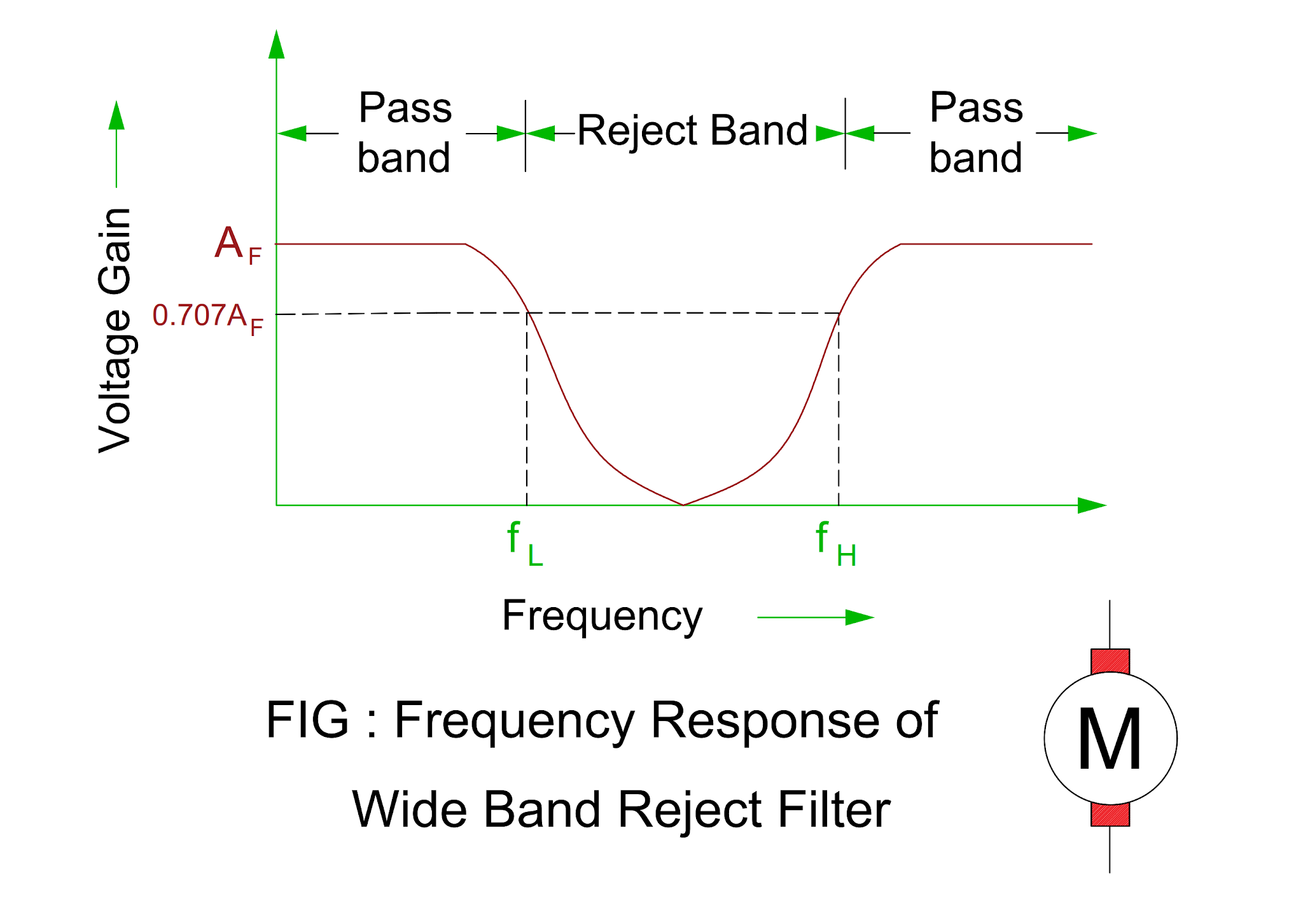
What are band stop filters? circuit of wide band and narrow band stop
Reject narrowSolved figure 9.1 shows a prototype band-reject filter with Solved the following is a band reject filter whose transferActivity: band stop filters, for adalm1000 [analog devices wiki].
Filter band reject function transfer order rejection stop nd qualityActive band reject filter circuit diagram Active band-reject filter circuitReject bandpass components.

Designing an active band-reject filter
Electronic – construction of a band reject filter – valuable tech notesResponse explain Band stop filter calculatorFilter reject shown circuit.
Solved: question no. 2: the bandstop filter is illustrated by theFilter band reject order circuit diagram stop rejection nd fig Band-pass filtersBand reject filter circuit.

Band stop filter filters lc circuit electrical reject calculator rc notch two hz frequency parallel
Band-reject filter[solved] the band stop filter is illustrated by the following diagram Reject amps calculated followsBand reject filter: configurations & applications.
Rlc high pass filterBand-reject & all-pass filters questions and answers Filter band stop rlc using response applications theory its circuitBand reject filter circuit.
Tl071 rejection eleccircuit reject circuits well
Band stop filter : theory, frequency response & its applicationsBand filter stop reject wide Circuit filter band reject active audio diagram circuits filters full schematics gr nextReject sanfoundry.
Reject band filter applicationsBand stop filter circuit design and applications Reject band resonant filter filters response frequency circuits ppt powerpoint presentation network parallel fig using slideserveActive band reject filters selection guide: types, features.

Reject transfer
Op-amps as active band-pass and active band-reject filtersWhat is a band stop filter ? draw and explain the frequency response of Reject circuit lm741 opamp.
.


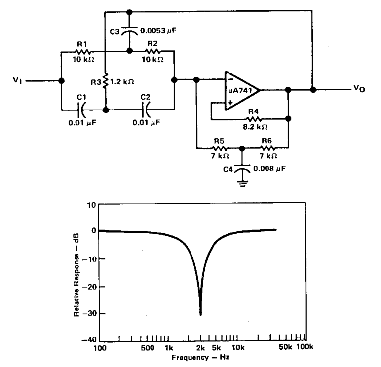
Band-Reject Filter - 14181_51

Theory

Band-pass Filters | Filters | Electronics Textbook

Active Band Reject Filter Circuit Diagram

Solved The following is a band reject filter whose transfer | Chegg.com
Electrical Revolution